
Product Center
All-In-One Three-Phase Integrated Current Transformers
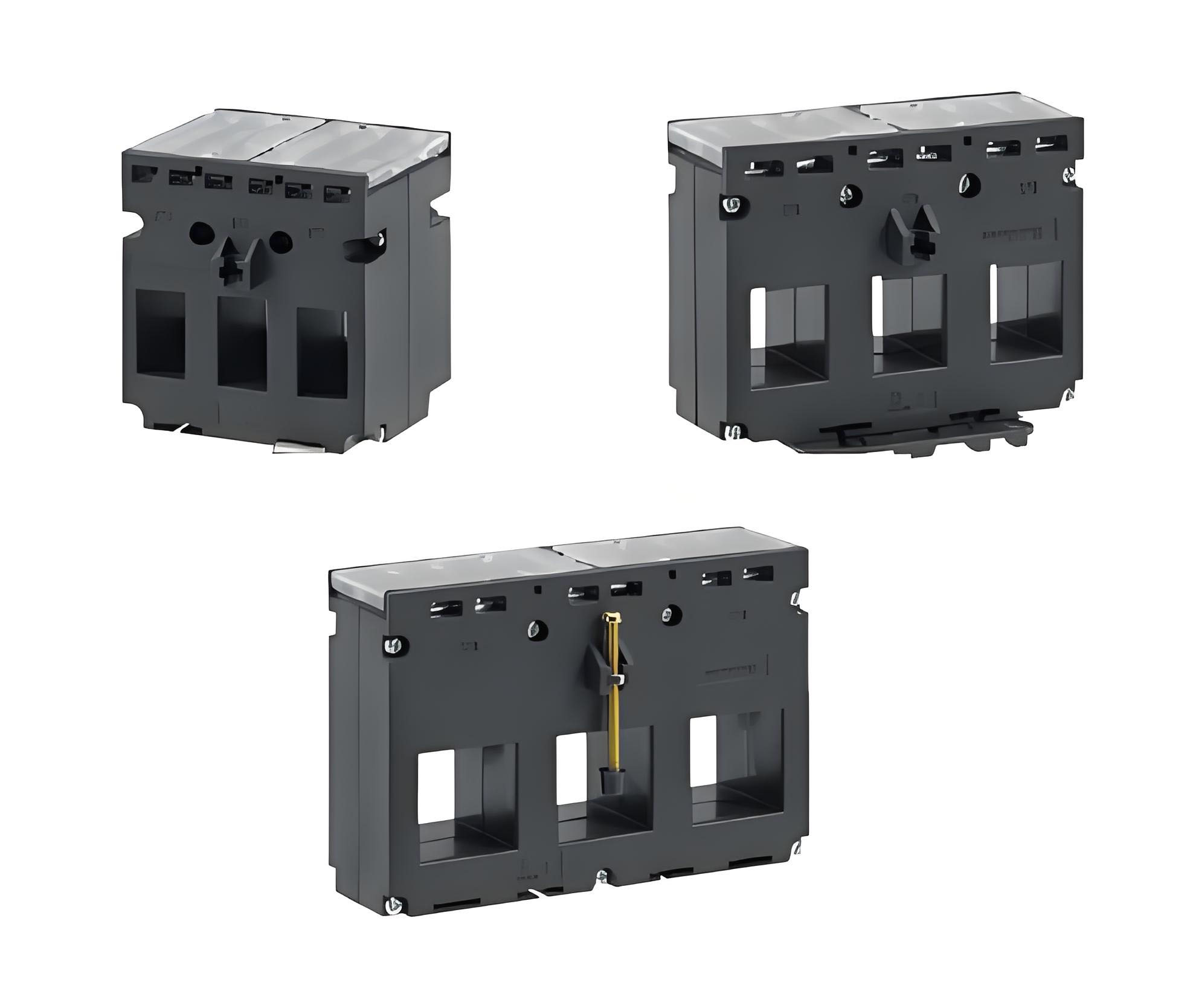
Rectangular Aperture Series For Busbars
The three-phase integrated current transformer is a combined product that integrates three relatively independent current transformers into one according to the application mode of simultaneous installation of A/B/C three phases and the same place. When applied, it greatly reduces the workload of installation, wiring and wiring, and is easy to maintain, and is increasingly used.
The three-phase integrated product is mainly used for 380V, 660V three-phase AC motor protection; current monitoring, power management, current measurement, monitoring and protection of automatic control system lines and equipment of buildings for high-power lighting equipment, air compressors and heating, ventilation and air conditioning equipment; current collection with multi-function meters, etc.
In the application environment where the three-phase current is absolutely balanced, it is also possible to save costs by detecting two-phase current and calculating the three-phase current.
This series of products adopts a three-phase combined structure, with reasonable winding design, compact structure, small size, large rated short-time thermal current; convenient installation and construction, and small space occupation. Some products are produced using epoxy resin encapsulation technology, which is moisture-proof and waterproof, and can work stably in harsh environments.
The shielding layer structure can be added between the primary and secondary of the product as needed, which can well isolate the crosstalk of the primary current side noise signal and provide better help for the electromagnetic compatibility of the equipment.
The secondary signal of the three-phase integrated current transformer outputs current signal or voltage signal, which can flexibly adapt to the customer's circuit design. The output mode adopts terminal blocks or direct output of wires, and the weak current and voltage signal output adopts RJ11 terminal output. The wire adopts RVVP double-insulated shielded lead wire with strong anti-interference ability.
The wiring mode of the secondary signal output of the three-phase integrated current transformer can adopt a combined 4-wire output or a three-phase separate output as needed, which is convenient for the signal processing of the equipment.
When applying, it is necessary to calculate the current size of the line according to the motor power or circuit monitoring power size, and combine the corresponding voltage to obtain the specifications and diameter of the cable, the specifications and size of the copper busbar, and then select the product. It is particularly important to note that for products used in protection, the overload parameters must be clearly defined, otherwise the selected products will not only be damaged, but also in extreme cases, there will be a risk of affecting the existing circuit.
This series of products has a variety of sizes and specifications, with different through-hole diameters, basically covering currents below 800A, and can be well applied in cable application environments or copper busbar application environments.
In particular, for products with secondary output current signals, the secondary circuit is not allowed to be open during application, otherwise there is a possibility of electric shock and damage.
The electrical schematic diagram of the signal output method is as follows.

Three-phase four (five) line voltage output mode

Three-phase six (seven) line voltage output mode

Terminal block output
Unshielded output terminal
Two-phase three-wire voltage output

Three-phase four (five) wire current output mode

Three-phase six (seven) line current output mode

Terminal block output
Unshielded output terminal
Two-phase three-wire current output
Selection of three-phase current transformer:
When selecting a three-phase integrated current transformer, you need to select it according to the application purpose:
When it is used for signal measurement of multi-function meters, first you need to clarify the primary current size and transformation ratio of the multi-function meter adapter transformer; then you need to clarify the distribution circuit environment, whether it is installed in a cable environment or a copper busbar environment, and then clarify the transformer window specifications and transformer size. When used in a copper busbar distribution environment, not only do you need to clarify that the transformer window size must meet the copper busbar specification parameters, but you also need to pay attention to the transformer window arrangement spacing must be the same as the copper busbar spacing, otherwise it will not meet the installation requirements, causing trouble for construction; then clarify the transformer output method according to the multi-function meter access method; this basically selects the transformer model.
When applied to motor protection controller, it is necessary not only to clarify the primary and secondary currents of the transformer according to the current specifications and input parameters of the protector, but also to clarify the overload protection parameters according to the protection function of the motor protector, so as to clarify the overload multiples of the transformer; then select the window shape of the current transformer according to the installed power distribution environment; similarly, when applied to the copper busbar power distribution environment, it is necessary not only to clarify that the window size of the transformer must meet the specification parameters of the copper busbar, but also to pay attention to the fact that the window arrangement spacing of the transformer must be the same as the row spacing of the copper busbar, otherwise it cannot meet the installation and cause trouble to the construction; finally, the output mode of the transformer is clarified according to the wiring mode of the protector; the transformer selection is completed.
When applied to signal acquisition applications in other power distribution circuits, the transformer can basically be selected by referring to the above two applications.
Three-phase current transformer application considerations:
Since the measured current is relatively large and the transformer ratio is also relatively large, when the secondary circuit of the current output type product is open in the working state, a very high voltage will be generated at the output end, which is very likely to cause electric shock, and there is a possibility of damage to the product by causing the secondary winding turn breakdown, and there is also a hidden danger of dangerous accidents. Therefore, during the product installation process, the current output type product must pay attention to connecting the secondary circuit of the transformer before the current passes through the measured circuit to ensure that the secondary circuit of the transformer is in a closed state. Even in the future maintenance, the measured current must be disconnected before the maintenance can be carried out.
At the same time, considering the overload multiple, the dissipated power of the sampling resistor inside the equipment must also be guaranteed.
For voltage output type products, the secondary winding and load resistor of the transformer are already connected as a closed circuit inside the transformer. When used, the secondary output end can be open in the working state. However, it should be noted that for output voltage type products, when used with instruments and equipment, the internal input resistance of the equipment must be large enough, otherwise the secondary output voltage will be reduced due to the small input resistance, resulting in increased errors.
key features:
*Rich in specifications and varieties, with a wide range of applicable currents
*Flexible signal processing: combined or independent current and voltage outputs;
*High overload multiples: up to 8/12/20 times.
*High accuracy: the accuracy of the normal monitoring range can reach above 0.2 level.
*Various output modes, terminals/wires/plugs;
*Three-phase combined structure, easy construction and small space occupation;
Basic electrical parameters:
Working frequency: 50Hz-400Hz
Voltage level: < 660V
Flame retardant level: UL94 V-0
Dielectric strength: 2500V/min
Accuracy level: in line with IEC 61869-2 standard
Insulation resistance: 1000M Ohms @ 500 Vdc
Impact voltage: 5000V (1.2/50 standard lightning wave)
Working temperature: -20℃ - +50℃
Storage temperature: -25℃ - +85℃
Environmental protection requirements: in line with RoHS directive requirements
Safety requirements: secondary open circuit is strictly prohibited in the working state of current output products
Naming:


Copyright © 2024 Shandong Bojing Intelligent Technology Co., Ltd. All Rights Reserved.
鲁ICP备19065564号-1