
Product Center
Residual Current Transformers (RCT/ZSCT/CBCT)
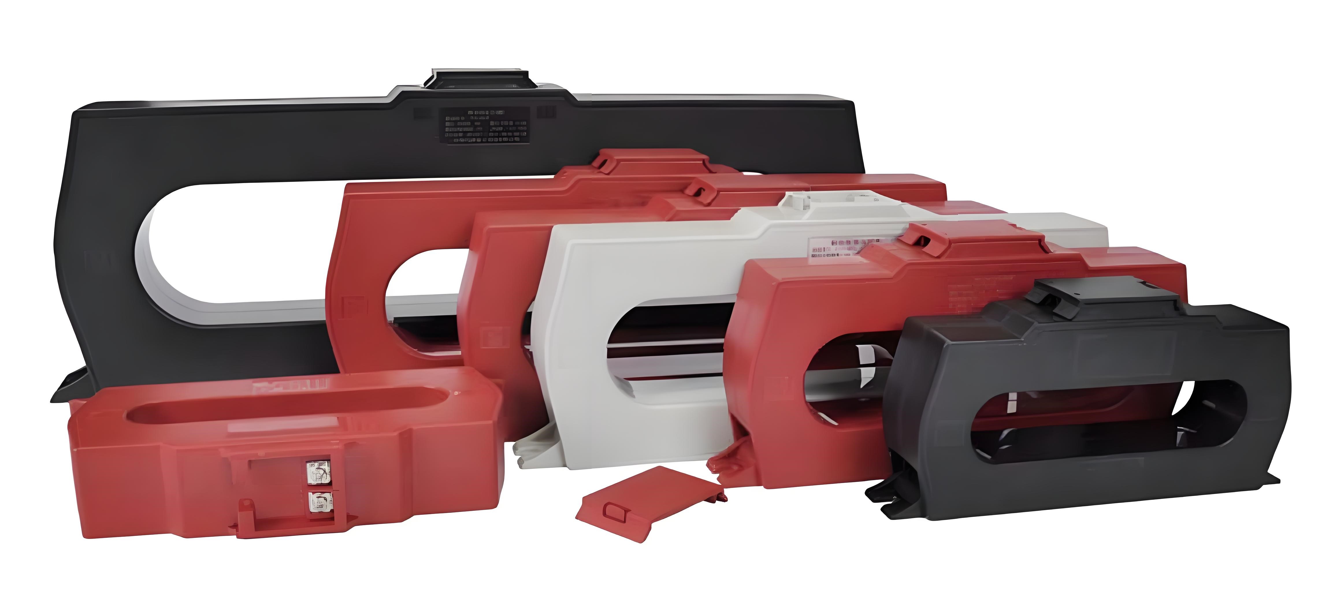
Rectangular Aperture Series For Busbars
The residual current transformer is a device mainly used to detect the vector sum of all node currents passing through the residual current transformer through-hole in the distribution circuit, and transform it into the required signal according to the set transformation ratio.
The residual current transformer is one of the most critical components for signal perception in relay protection equipment or leakage detection monitoring system. The quality of its performance and the stability of its work will directly determine the sensitivity, accuracy and working reliability of the leakage protection system or the residual current monitoring system.
The performance of the residual current transformer has a huge impact on the relay protection equipment or the leakage monitoring system, so the following characteristics of the residual current transformer need to be clarified during use.
Features and requirements:
Sensitivity:
Sensitivity is the characteristic of the minimum current that the residual current transformer can sense. Since the residual current transformer is mainly used to detect the vector sum of the loop current, and when the detected loop is well insulated and has no leakage, the vector sum of the current, that is, the residual current, is almost 0, so in actual use, the residual current transformer needs to detect mA-level or even uA-level signals as much as possible.
Generally, the smaller the current signal detected by the residual current transformer, the higher its sensitivity.
The sensitivity is directly related to the soft magnetic material selected for the transformer. Generally, the higher the initial magnetic permeability of the magnetic material, the higher its sensitivity, the worse its anti-saturation ability, and the higher the cost; the lower the initial magnetic permeability of the soft magnetic material, the lower the sensitivity, but the higher the anti-saturation ability, and the lower the cost. At the same time, the larger the through-hole diameter of the transformer and the longer the magnetic circuit, the higher the cost of ensuring sensitivity. In the application, it is necessary to reasonably select according to the technical requirements to save costs.
Accuracy and Linearity:
The so-called accuracy, also known as the accuracy level or precision grade, refers to the percentage of the maximum current error of the transformer when the primary current is the rated value under the specified conditions of use. According to the regulations, the corresponding accuracy level must be better than the allowable error of the corresponding level. Linearity refers to the ratio of the output current change of the transformer to the input current change, which is a constant. The quality of the transformer linearity index has a great impact on the performance of the residual current detector and is directly related to the stability and reliability of the residual current detector. Only when the transformer has good linearity can it reflect the true line leakage state.
The accuracy and linearity of the transformer are related to the magnetic material, secondary load, and through-hole diameter of the transformer. Generally, when the size and load are constant, the higher the magnetic permeability of the magnetic material, the higher the accuracy; when the magnetic material and load are constant, the smaller the through-hole diameter, the higher the accuracy; when the material and size are constant, the larger the secondary load, the worse the accuracy and linearity.
The residual current transformer used in the residual current detection system needs to continuously monitor the residual current in the range of 30mA--1000mA, and the detection accuracy needs to be better than 3%. However, considering that the total assessment error of the detector system cannot exceed 10% as stipulated by the national standard, the accuracy level of the residual current transformer should be better than level 1 or level 0.5, and in order to reduce costs as much as possible, the smallest possible secondary load can be selected.
Balanced properties:
Ideally, when there is only rated working current but no leakage current at the back end of the detection node of the detected circuit, the residual current transformer should not have an output value. However, due to the uneven magnetic permeability of each point of the iron core of the residual current transformer, unbalanced magnetic circuit or poor winding process, the relative position of the primary conductor and the secondary winding is asymmetric or the working current is different, there is still an induced potential in the secondary winding and an induced current output, which is the concept of balanced characteristics.
In addition, when there is a large current flowing near the transformer or the presence of a strong magnet, the influence of external factors on the transformer will also change the magnetic permeability of each part of the iron core, causing the residual current transformer characteristics to deteriorate, and the circuit after the measured node will still have current output without leakage.
Under a certain load, the greater the induced potential generated by the residual current transformer due to the above factors, the worse the balance characteristics of the transformer.
In the residual current detection system, the national standard requires that the system error cannot be greater than 5%, so in extreme cases, the error caused by the current transformer balance characteristic factors cannot exceed 5%. Otherwise, it is extremely difficult to ensure that the detector and its system work stably and reliably within the declared alarm threshold.
Under a certain load, the greater the induced potential generated by the residual current transformer due to the above factors, the worse the balance characteristics of the transformer.
In the residual current detection system, the national standard requires that the system error cannot be greater than 5%. Therefore, in extreme cases, the error caused by the current transformer balance characteristic factor cannot exceed 5%. Otherwise, it is extremely difficult to ensure that the detector and its system work stably and reliably within the declared alarm threshold.
Overload characteristics:
The overload characteristic examines the ability of the residual current transformer to recover after a large current shock. After the residual current transformer is subjected to a large current shock, the smaller the change in the performance parameters of the residual current transformer, the better its overload characteristic, and vice versa. When the overload characteristic of the transformer is poor and it cannot recover to the state before the shock after being subjected to a large current shock, the leakage protection system may refuse to operate, and the residual current monitoring system may give a false alarm or no alarm.
Temperature characteristics:
The temperature stability of the transformer refers to the phenomenon that the output of the secondary signal of the transformer changes with the change of temperature when the primary signal is stable. The quality of the temperature characteristics of the residual current transformer will affect the temperature stability of the leakage protection system or the residual current detection system.
Isolation withstand voltage:
The residual current transformer not only has the function of detecting the node current vector sum, but also needs to have good isolation and insulation for the measured circuit to ensure the safe operation of the signal processing unit connected to the secondary side of the transformer and its back-end system. Poor isolation withstand voltage index of the residual current transformer may cause the protection equipment or residual current detection system to be damaged by strong current shock, and even endanger personal safety.
Selection of residual current transformer
*First of all, it is necessary to clarify the application purpose and installation environment of the transformer
Generally, residual current transformers are mainly used in the following aspects: in environments for rated action protection, such as electric water heaters, miniature circuit breakers, and other electrical appliances with high power, in order to prevent the occurrence of electric shock hazards, there will generally be leakage action protection settings, and residual current transformers with high sensitivity and excellent balance characteristics will be used; in environments for distribution circuit grounding protection, such as electrical protection devices, motor protection devices, etc., it is necessary to monitor the leakage state of the distribution circuit in real time and implement protection functions under specified conditions, which requires residual current transformers with high accuracy and linearity, strong anti-saturation ability, and excellent balance characteristics; in environments for insulation monitoring and electrical fire monitoring, such as residual current transformers in residual current detector systems, residual current transformers with high accuracy, good linearity, and excellent balance characteristics are required.
From the above analysis, no matter which type of residual current transformer, the requirements for other electrical parameters may be different, but the balance characteristic is a must for the residual current transformer, which shows how important the balance characteristic is to the residual current transformer.
Due to different functional requirements, the selection, design and cost of residual current transformers are greatly affected. Only by clarifying the purpose of application can we better select residual current transformers that are optimized in use, and the cost can be reduced as much as possible.
After the application purpose of the transformer is clear, it is necessary to further clarify the installation environment: for use in cable loops, as long as space permits, circular through-hole series products are preferred. Under the same loop current, this can not only reduce costs, but also put the entire system in the best application state; if space does not allow or when used in a busbar environment, when the circular through-hole cannot meet the requirements, it is necessary to consider the rectangular through-hole series products. Although the linearity and balance characteristics are not as good as the circular through-hole series, and the cost is relatively high, the error can also be well controlled within the allowable range, and it can meet the installation requirements, which is still a better solution; when used in existing circuit reconstruction projects, construction is not allowed without power outages, only open-type residual current transformers can be used. Although the cost is high, as long as the error and balance characteristics are within the allowable range, it becomes the only solution.
*Determine the diameter of the transformer's through aperture
After determining the type of transformer, it is necessary to select the specifications of the transformer according to the specifications of the cable or busbar.
If a circular through-hole transformer is selected, it is necessary to roughly calculate the minimum diameter required for the circuit according to the specifications and number of cables. If the diameter of a single-core cable is D, the minimum diameter required in a three-phase three-wire circuit is approximately 2.2D; the minimum diameter required in a three-phase four-wire circuit is approximately 2.5D; based on these calculated results, the inner diameter of the residual current transformer is further selected. Generally, the result obtained by multiplying the above calculated data by 1.2 can be used as the through-hole diameter of the transformer, or a residual current transformer with a similar but slightly larger aperture can be selected.
In the busbar environment, it is necessary to understand the installation size of the busbar. This can be determined according to the model of the circuit breaker and its installation size. The specifications and installation size of the busbar used can be determined. According to the installation size of the busbar, a slightly larger rectangular residual current transformer product can be selected. Since the shape of the through hole of the residual current transformer directly affects the balance characteristics of the residual current transformer, the round through hole has the best balance characteristics, the rectangular through hole is second, and the open product has the worst balance characteristics. At the same time, considering that the prices of the products vary greatly, when selecting products, the round through hole products are preferred, the rectangular products are second, and when the closed-loop products cannot meet the installation needs, the corresponding openable products are considered.
*Determination of the secondary signal of residual current transformer
Since the primary residual current of the residual current transformer is relatively small, in order to ensure the excellent linearity of the transformer, the secondary output signal of the transformer is generally relatively small, and the current signal output is mostly in the range of 0.25mA-50mA; the voltage signal output range is mostly between 100mV-2000mV. The output signal of the general residual current transformer mostly needs to be A/D converted and then processed. In order to improve the accuracy of A/D conversion, it is hoped that the secondary output signal of the transformer is as large as possible. However, the larger the signal, the worse the linearity of the transformer will be. When the output signal is relatively large, in order to improve the linearity, it is often necessary to set the transformer ratio to be larger, which will increase the cost and also prolong the production cycle. Therefore, as long as the conversion accuracy and linearity can meet the system requirements, it is advisable to have a smaller output signal. When the output is a current signal, the parameters of the ratio also need to be considered; this can be determined by considering the above analysis and the sampling resistance value. When the output is a current signal, the sampling resistance in the system directly affects the sampling accuracy, so its accuracy is preferably better than 0.5%.
The secondary output signal of the open-type residual current transformer should not be higher than 1000mV. Since the magnetic circuit of the transformer is disconnected, its magnetic conductivity is greatly reduced. Therefore, when the output signal is relatively large, the linearity deteriorates sharply. This will cause the system to monitor the set point with effective accuracy, while the error of the monitoring data deviating from the set point will increase, resulting in a decrease in the overall performance of the system.
When installing at a single point, you can also consider the integrated module integrated residual current transformer product, that is, the signal processing circuit and the secondary winding integrated product, which can directly output the required digital signal. Since the signal processing module and the current transformer are in the same product, the signal line crosstalk is reduced as much as possible, and the cost is saved.
*Secondary output mode of residual current transformer
Common output methods of residual current transformers include shielded lead output and terminal output. The most commonly used lead is RVVP double-insulated shielded sheathed wire; terminal output is also possible, and the wiring method is more flexible. When using terminal output, the signal line needs to use twisted pair wire to improve anti-interference ability. If the signal line is too long, it is also necessary to consider RVSP twisted pair double-insulated sheathed wire or add a signal amplification circuit inside the residual current transformer.
*Type determination of residual current transformer
After the above steps, the specifications, specific parameters, output mode, etc. of the residual current transformer can be determined. After considering some other details, you can select the model according to the "Product Selection Manual".
Balance characteristic test principle and circuit
When the ratio of the residual current transformer is 2000:1; ideally, when the secondary side of the transformer is connected to a 2K ohm load and the primary input current is 1000mA, the voltage displayed at both ends of the load should be 1000mV, so 1mV can be equivalent to 1mA. When using the test fixture for testing, the mV value shown on the voltmeter can be equivalent to the unbalanced output current value of the residual current transformer.

Balance characteristics test method
Test method for balanced characteristics of circular window transformer
1. The test fixture is close to the inner wall of the transformer through-hole and passes through the transformer vertically with the maximum spacing;
2. Make the test fixture pass the test current of the specified level;
3. Rotate the transformer for one circle, and the multimeter reading must not be greater than the specified value;
4. Make the angle between the transformer through-hole and the test fixture 45 degrees;
5. Rotate the transformer again for one circle, and the multimeter reading must not be greater than the specified value;
6. Rotate the transformer twice in the above way for one circle each, and the rotation speed is not greater than 6°/second. The readings are not greater than the specified value to be qualified.


Balance characteristic test method of rectangular window transformer
1. The test fixture is located vertically at the maximum spacing position in the transformer through-hole;
2. Make the test fixture pass the test current of the specified level;
3. Make the two arms of the fixture close to the middle at the same time, and the multimeter reading must not be greater than the specified value;
4. Make the two arms of the fixture close together and move to the inner wall of the transformer through-hole;
5. Make the test fixture slide close to the inner wall of the through-hole for one circle, and the multimeter reading must not be greater than the specified value;
6. Test the transformer in the above two ways, and the reading is not greater than the specified value to be qualified.


Error test principle and circuit

According to the application mode, the residual current transformer can be tested for its accuracy and linearity by the "source-meter method".
In the specific implementation method: the current source is used to provide a standard current, and the specified current is input according to the rated parameters of the residual current transformer. The secondary of the transformer is connected in parallel with the rated load resistor, and a high-precision voltmeter is connected at both ends of the load resistor to monitor the voltage at both ends of the secondary load resistor of the transformer. And it should be noted that all test equipment needs to be well grounded, otherwise the measurement error will increase.
After measuring the voltage across the transformer's secondary load, calculate the transformer's secondary output current based on the actual resistance of the load resistor, and then calculate the error. Since the secondary output current of a general residual current transformer is very small, the reading is easily affected by environmental noise and the reading is inaccurate. It is not recommended to use an ammeter to directly measure the transformer's secondary current.
When it is necessary to detect the sensitivity of a certain point, it is recommended to use an oscilloscope to monitor whether the transformer's secondary output waveform is distorted under the operating conditions and whether the core is saturated. When the transformer waveform is severely distorted, the transformer's repeatability cannot be guaranteed.
During the entire detection process, like other transformers, the transformer secondary circuit is not allowed to be open. Generally, since the iron core of the residual current transformer is a high-permeability core and the core cross-section is not large, the transformer secondary circuit is more likely to be saturated and cause iron core residual magnetism, which will increase the error of the transformer.
Overload test principle and circuit
The circuits for overload test and error test are the same.
First, an error test before overload test needs to be performed before overload test, and the test data needs to be recorded to calculate the error; then, according to the overload parameters, the specified overload current needs to be input for overload test; after the overload test is completed, an error test after overload test needs to be performed, and the error needs to be calculated based on the test results.
The error after overload needs to be within the allowable range, otherwise the product will fail to meet the standards.
Installation of Residual Current Transformer in Power Distribution System
Before installing the residual current transformer, you must first find out the grounding form of the low-voltage system. The grounding forms of the low-voltage system in China are TT, TN, and IT systems. Since the IT system forms a closed system, it is used in special circumstances and has high safety performance. Generally, residual current protection devices are not used as personal electric shock and electrical fire protection. In the TN system, it can be divided into TN-C, TN-C-S, and TN-S systems. The wiring requirements of the residual current transformer in the TT, TN-C-S, and TN-S systems are different.
In the TN-S, TN-C-S, TN-C, and TT systems, the phase line and neutral line of the loop must pass through the through hole of the residual current transformer at the same time. The PE line must not pass through the through hole of the residual current transformer, and any neutral line of each loop must not be mixed. In the TN-C system, since the PE line and the neutral line are the same line, the residual current protection device cannot be used, and the residual current transformer is not recommended. The TN-C system can be changed to the TN-C-S system, and then the residual current transformer can be installed. Please refer to the following drawings for details.
Installation of Residual Current Transformer in TN-S System

Installation of Residual Current Transformer in TT System

Installation of Residual Current Transformer in TN-C System

Installation of Residual Current Transformer in TN-C-S System

Not all residual current transformers require the phase line to be passed through the residual current transformer. The total residual current detection method in the TN-S system does not require the phase line to pass through the residual current transformer, but only requires one cable to pass through the residual current transformer. This method has special advantages: a small residual current transformer can be used to improve measurement accuracy, and if the transformer fails later, maintenance is also convenient; and because the residual current is generally small, the impact on the residual current transformer is relatively small; the transformer uses a small model product to reduce the cost of use. The specific wiring diagram is as follows:

The location of the residual current transformer should be as far away from the phase line of other circuits as possible to avoid the strong magnetic field generated by the large current of other circuits affecting the working state of the residual current transformer. If conditions permit, the phase line of the detected circuit should be located in the middle of the residual current transformer through-hole as much as possible to eliminate the influence of the phase current of the detected circuit on the residual current transformer as much as possible.
When installing a large-aperture residual current transformer, since the phase current of the detected circuit is generally large, the A/B/C/N circuit cables should be kept close together and located in the middle of the transformer through-hole as much as possible. This will improve the influence of the circuit current on the transformer as much as possible.
When installing the residual current transformer around the busbar, adjust the position of the residual current transformer so that the four busbars are located in the middle of the residual current transformer through-hole, and the distance between the busbar and the inside of the transformer is as consistent as possible. It is not recommended to install the busbar close to the inside of the transformer, because the A/B/C phase busbar is close to the transformer coil, which has a more adverse effect on the winding coil.
Since the residual current transformer detects the current vector sum, it is generally not necessary to distinguish the same-name terminals during use. Instead, you only need to connect the secondary winding of the transformer to the equipment properly.
Generally, the residual current transformer can be installed at the upper or lower end of the switch or circuit breaker, which will not affect the detection results. However, for the convenience of future detection, it is recommended to install it at the lower end of the switch or circuit breaker. When powering off for maintenance, it is not necessary to power off the upper switch, but only the switch at this level.


Copyright © 2024 Shandong Bojing Intelligent Technology Co., Ltd. All Rights Reserved.
鲁ICP备19065564号-1